+


Single Axis CNC Motion Programmable Controller 40KHz Manual operation Parameter setting function for Servo Motor Stepper Motor
Single Axis CNC Motion Programmable Controller 40KHz Manual operation Parameter setting function for Servo Motor Stepper Motor
Package include:
1x Single axis motion programmable controller
1x Universal plug converter
1x Manual will send via email.
Product description:
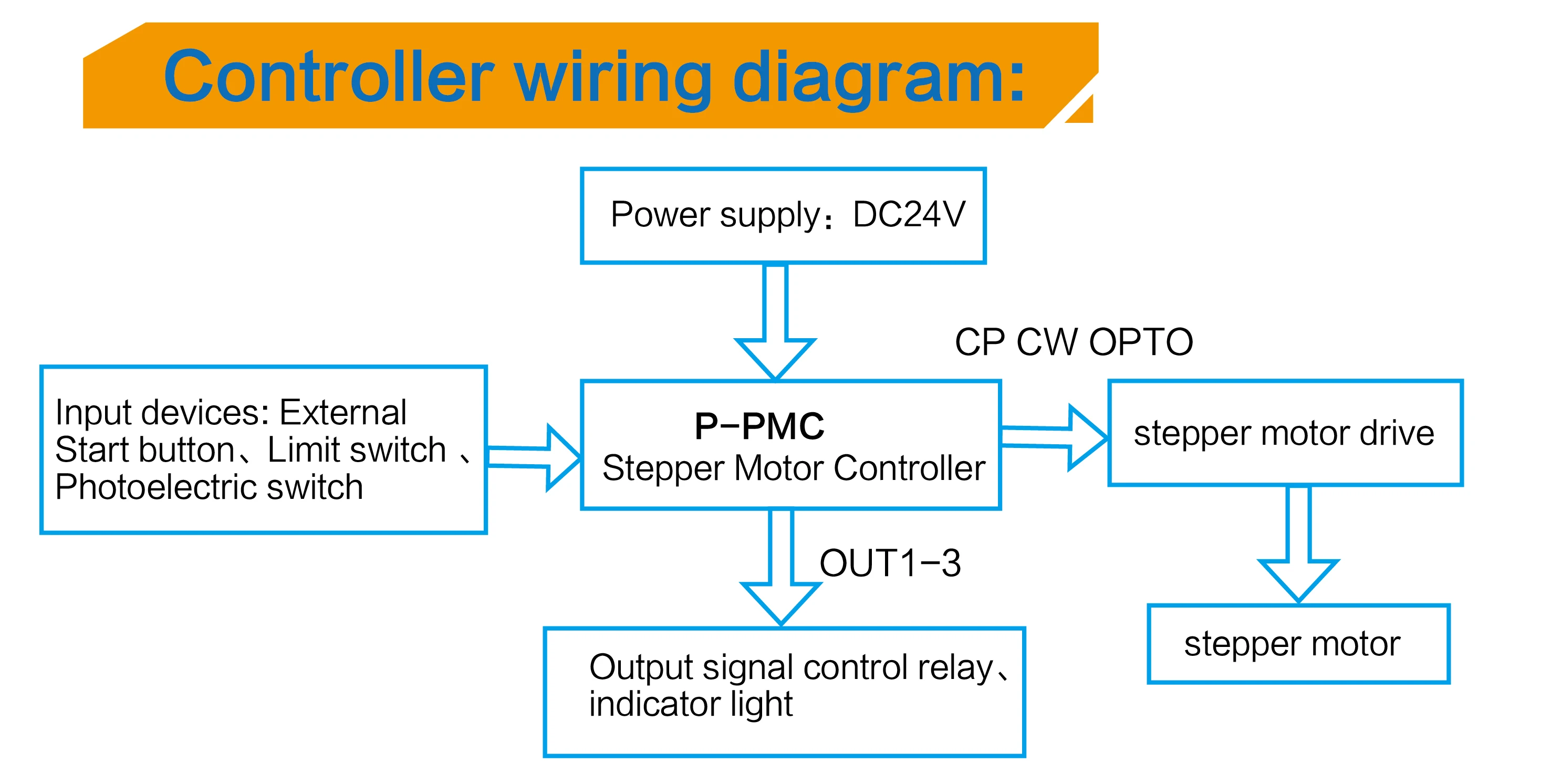
Number of controlled axis: Single axis; can achieve a variety of complex operation: positioning control and non-positioning control;
The maximum output frequency: 40KHZ;
Output frequency resolution: 1Hz;
Programmable maximum number of rows: 99;
Signal input: 6 (optical isolation);
Signal output: 3 (optical isolation);
A continuous displacement range: -7,999,999 ~ 7,999,999;
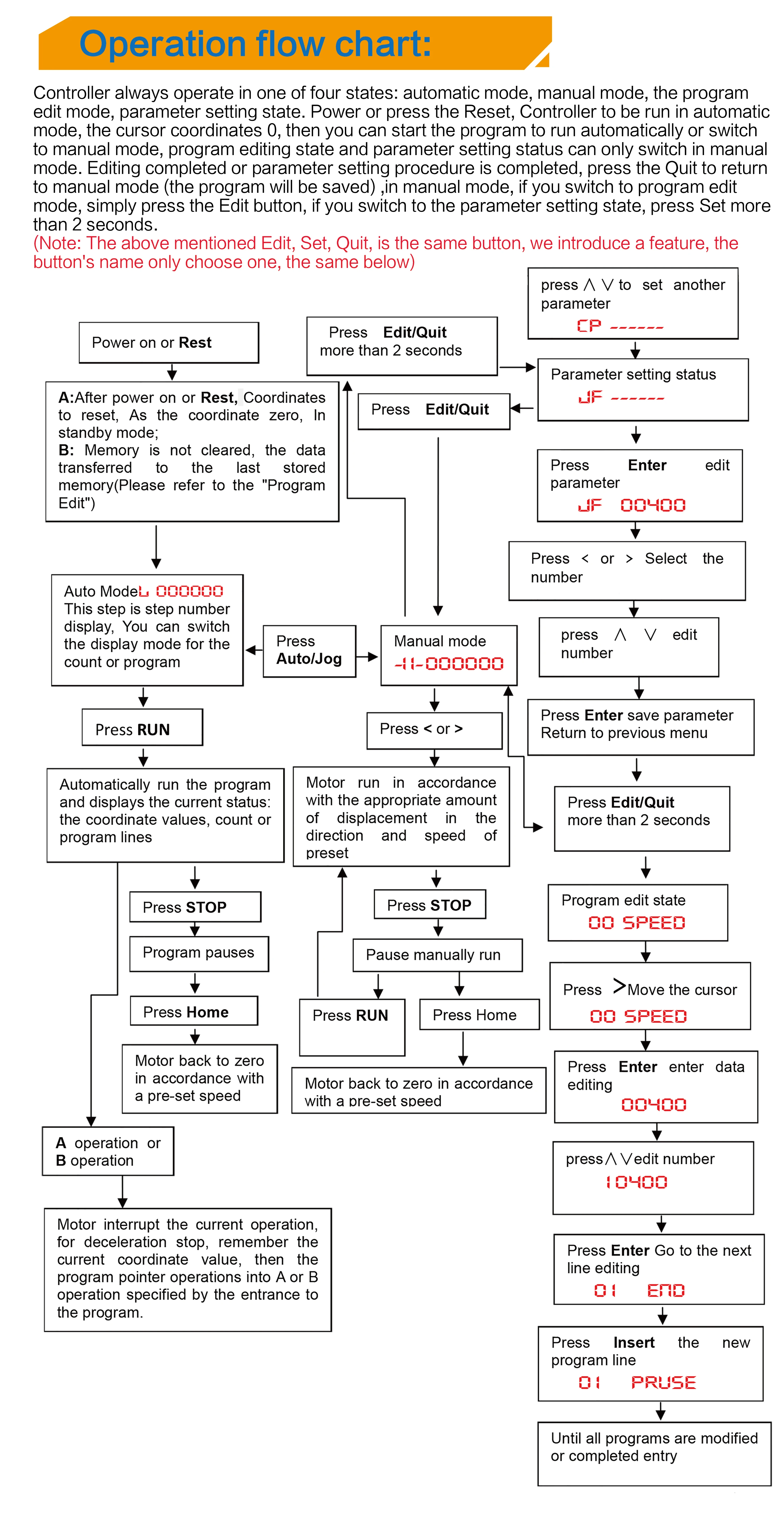
Operating state: Auto-run mode, manual operation, the program edit mode, parameter setting status;
Lifting speed curve: 2 (optimization);
Display digits: 8 digital display, manual / automatic status display, run / stop status display, the number of steps / counts / procedures display, edit the program, parameter display, input / output status display, pulse and direction display ;
Auto-run feature: You can edit, you can control the start and stop operation ect. automatically through the panel buttons and adding switches that connected to the back of the terminals;
Manual operation functions: position adjustment (manual jog speed and jog the number of steps can be set);
Parameter setting function: Starting frequency, acceleration and deceleration curve, reverse clearance, manually runlength, manual speed, back to zero speed and interrupt jump the line all can be set;
Program editing functions: You can insert, delete, modify the program. The controller can identify the error Instruction;
Return to Zero features: It can return to zero from the positive and negative directions automatically
The number of programming instructions: 14;
External operating functions: interrupt operation through parameter setting and add switches that connected to theterminals A and B;
Power supply:AC220V±15%;
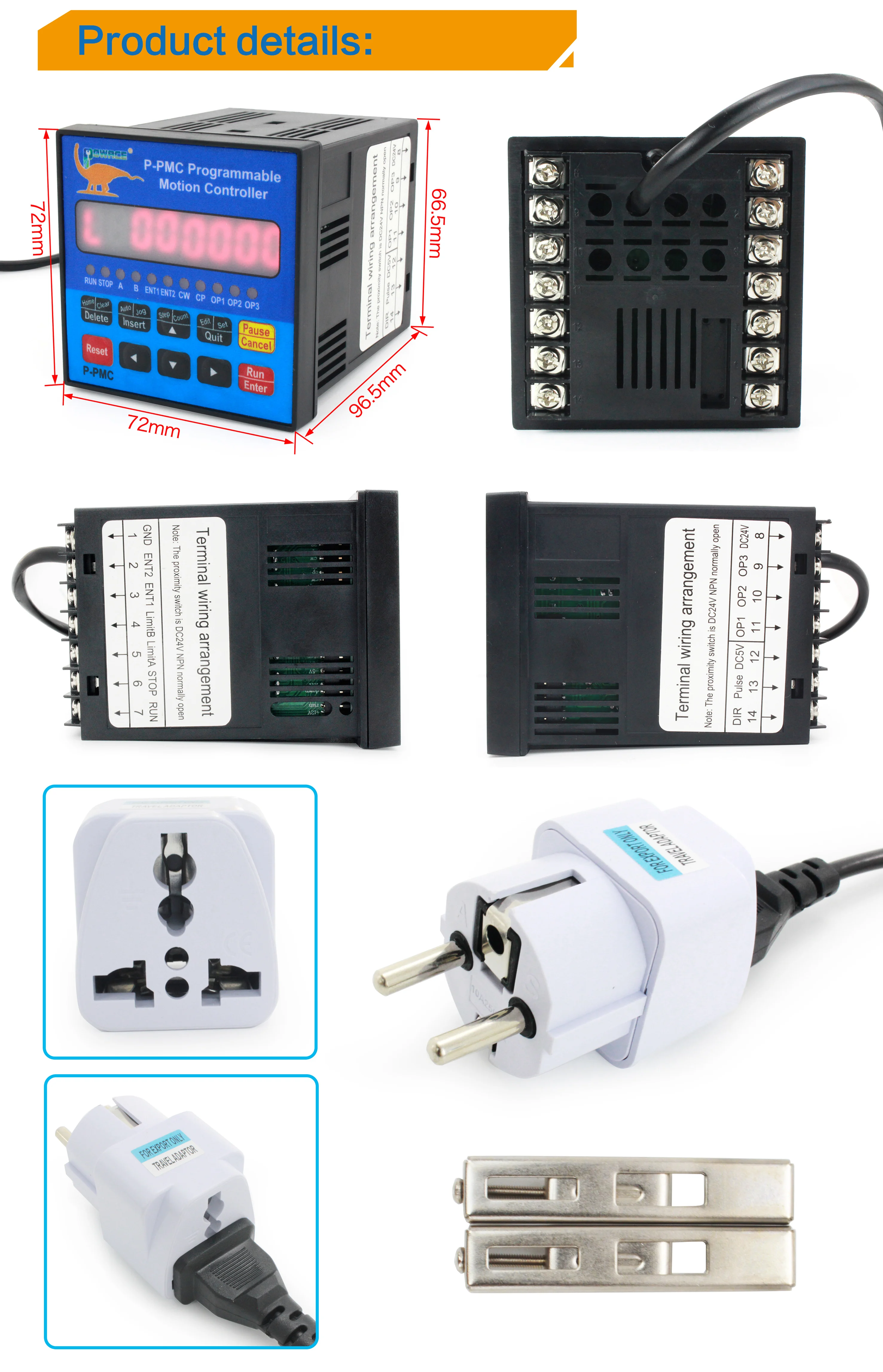
Front panel introduce:
1. 8 digital led Segment displays;
2. 6 input status indicator;
3. 3 output status indicator;
4. CP pulse signal indicator;
5. CW direction signal indicator;
6. Keys: Total 10 keys, and most of the composite keys, they represent different functions in different states (In the eglish manual will have detail instructions)
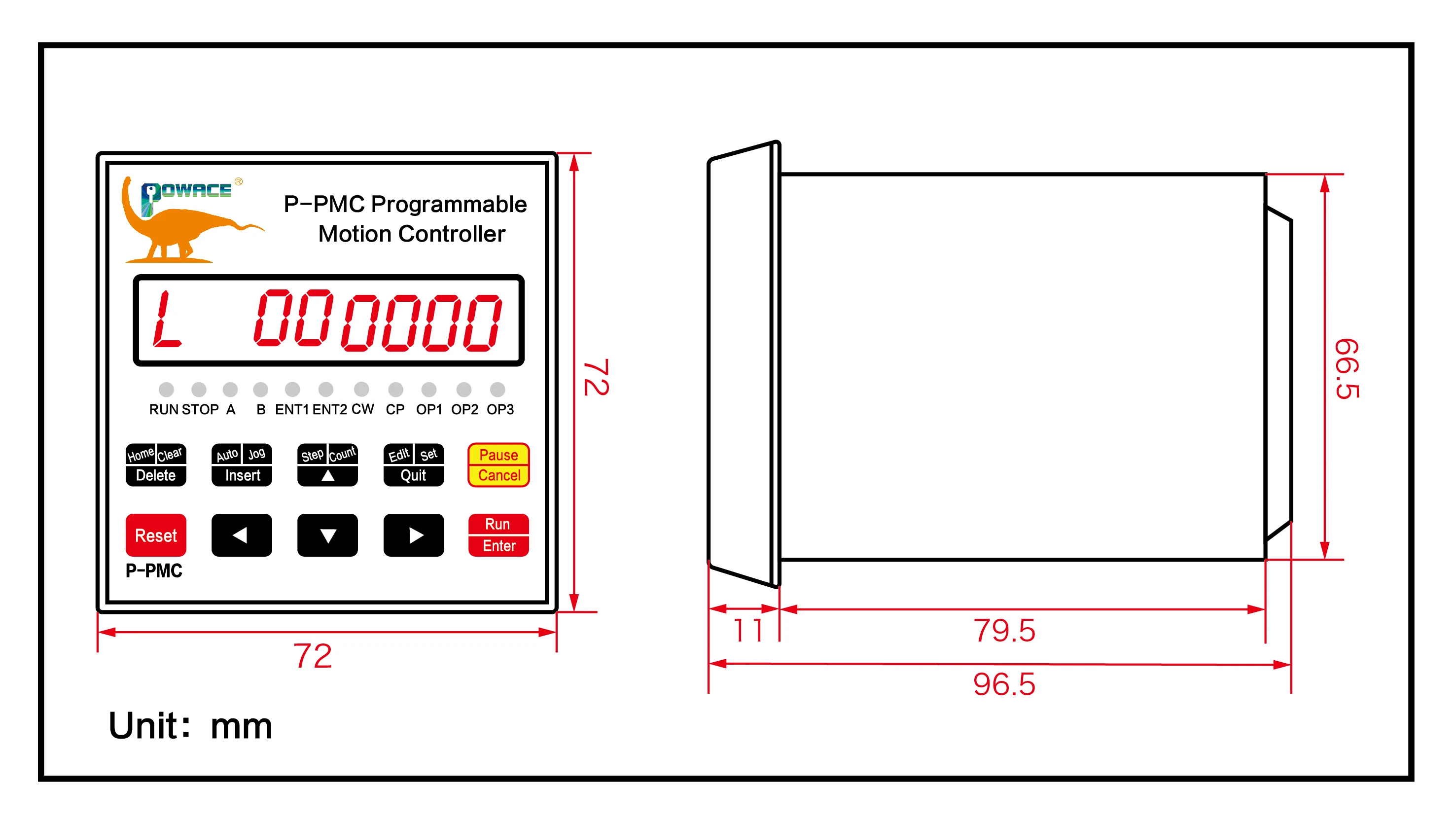
This controller adopts embedded instrument shell, small size and light weight (500g), the front panel is 71mm×71mm square, andthe length is 120mm. The specific dimensions are shown in the figure below.
Back panel diagram and signal descriptions:
1. Run: Start running the program, The same function as “Run” of the operation panel;
2. Stop: Pause the running program, which is equivalent to the stop button on the panel. After restarting, the program continues to run.
3. (Limit A) A operation and (Limit B) B operation are a major feature of this controller: For stepper motors, we generally perform quantitative positioning control, such as controlling the motor to run at a certain speed and a certain displacement. This method is easy to solve, just program the speed and displacement. But there are quite a lot of controls that cannot be positioned in advance. For example, the stepper motor is controlled to run in one direction from the starting point until it stops when it hits a travel switch, and of course, it runs in the reverse direction and returns to the starting point. For another example, the stepper motor is required to reciprocate n times between two limit switches, and so on. In these operations, we do not know the specific value of the displacement of the stepper motor in advance, how should we program it? This controller uses: "interrupt operation", which we call "(limit position A) A operation" and "(limit position B) B operation". Take "(limit position A)A operation" as an example, the work flow is: when the program is running, if "(limit position A)A operation" is input again, the motor will slow down and stop, the program is interrupted here, and the program is recorded Hold the coordinates of the interruption, the program jumps to the program specified by the entry address of "(limit A) A operation" to run the program.
4. ENT1 and ENT2 Switching signal input terminal.
5. OUT1, OUT2 and OUT3 Switching signal output terminal,
6. COM+, COM- input and output switch value external power supply, this power supply is DC24V/0.2A, this power supply is provided by the internal isolation of the controller.
7. 220V controller power input terminal. Input signal and output signal interface circuit: "Start", "Stop", "(Limit A)A operation", "(Limit B)B operation", "Input 1", "Input 2" of this controller are For input signals, they have the same input interface circuit. "Output 1", "Output 2", and "Output 3" are called output signals. They have the same output interface circuit. The input and output circuits are optically isolated to ensure that there is no mutual interference inside the controller. The internal working power supply (+5V) of the controller and the external working power supply (+24V) are independent of each other, and there is no connection. These two sets of power supplies are controlled by the controller. Two independent windings of the internal transformer are provided. The status of the switch input signal output signal corresponds to the indicator light on the panel respectively. For the input quantity, the input low level (when the switch is closed) the light is on, otherwise the light is off; for the output quantity, when the output is 0, it is the low level, the indicator light is off, otherwise the light is on.
Product Picture:

Motor Type : Stepper Motor
Brand Name : RATTMMOTOR
Certification : CE
Origin : CN(Origin)